This article shows how to quickly build an EMF model using the Ecore Tools UML editor and generate the Java source code.
For this article I am using eclipse eclipse-modeling-tools-2019-06.
Modeling Motivations
Main motivations for modeling and code generation:
- separation of application logic w.r.t. implementation: your independent model can be adapted to generate different implementations, for different systems.
- improve productivity by generating code from models: when you change the model, you can generate thousands of lines of codes in no time.
- improve application quality by standardizing implementation: generated code should use consistent design patterns and best practices. Testing is
- Increase application performances by generating efficient code: a high-level model can generate optimized low-level code optimized for specific hardware, i.e. embedded applications.
EMF is a solid and mature modeling platform used by large companies in various domains such as: banking, automotive, aerospace, embedded, etc…
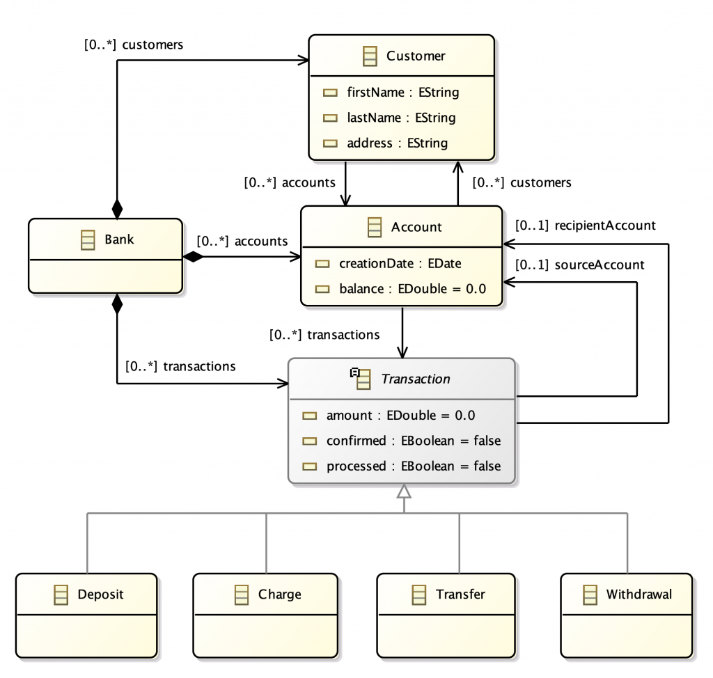
Domain Model: Banking
As a use case, I am re-using the Banking Model, presented in one of my talks at EclipseCon Europe: Rapid Prototyping of Eclipse RCP Applications.
Here is a description of the entities
- A Bank stores data of customers, accounts, and transactions.
- A Customer can have more accounts.
- An Account is related to one or more customers and is associated with a list of transactions.
- A Transaction references the source account and the recipient account.
- A Transaction is abstract and has four concrete sub-types: Deposit, Charge, Transfer, and Withdrawal.

In the next sections we see how to quickly implement the above data model and generate java code from it.
Ecore Modeling Project
Create a new Ecore Modeling Project: Open the New wizard with Ctrl+N (Cmd+N on mac), and select Ecore Modeling Project.

Type com.asciiware.emf.banking.model as Project name, then and click on Next.

In the next Dialog, set banking as Main Package, then click on Finish.

When done, you see the .aird Design editor to use for the model.
Ecore Tools UML Editor
The .aird editor is a UML Static Class Diagram editor that generates EMF Models. It is made available by Obeo as part of the EcoreTools.

In the editor we need to work on three main areas:
- Editor: the main area in the center containing the diagram
- Palette: sidebar providing tools to add elements and connections
- Properties: bottom view, for editing properties of selected elements
Notes:
- make sure the Properties view is visible as in the image above, so we can use it for editing.
- If you need to change the Namespace Uri, select the diagram and change it in the Properties.
Add Entities
Use the Class tool in the Palette to add the four main Classes in the diagram.
Edit the entities with the the Properties View to:
- set the class names: Bank, Customer, Account, and Transaction, then set the class names using the Properties view.
- check the “Abstract” box for Transaction.

Note: in this example, we don’t need Enums and Interfaces. If you need them:
- for Enums: use the Enumeration tool item from the palette
- for Interfaces: click the “Interface” checkbox in the entity Properties
Add attributes
Use the Attribute tools in the Palette to add the attributes to each class. For each attribute assign a value to Name and choose its EType.

Note: make sure you are using proper EMF Types. Indeed, EMF Provides an EType for mapping common Java Types. For example an EBoolean map to a Java boolean.
Add relations
Add containment relations from Bank to Customer, Account, and Transaction
- change the name of the relations to make them plural.
- keep the default lower and upper bounds: [0 .. *]

Notes:
- we use Composition as per UML definition, as the Bank is the sole responsible for disposing of the component parts.
- If you need a bidirectional relation, just set a value for the EOpposite reference.
Add references between Customer, Account, and Transaction as you can see in the below image.
- provide meaningful names to all relations
- change the cardinality to [0 .. 1] for the source and the recipient account.

Add subclasses of Transaction, and then add the SuperType relation.

Now, the domain model is complete. Open the banking.ecore model to verify your .ecore model is complete, like in the image below, and has no errors.

Documentation
You can provide documentation for any element on the Diagram, by selecting the element and filling the Documentation field in the Properties.

Code Generation
Given the .ecore model, EMF can generate a number of artifacts:
- domain model classes: java model with Interfaces, implementations and utilities
- edit code:
Open the banking.genmodel, right click the root node, and select Generate Model Code

Generated code: look in the Project Explorer, where you can see a new source folder called src-gen which contains the generated code.

The generated code is split in three packages:
- .banking: providing interfaces representing your model
- .banking.impl: classes implementing your interfaces
- .banking.util: providing utility classes
Re-generating
Typically, the modeling approach is used in big projects, where the models are long-lived. In this scenario, you should think that a model is often changed and classes are re-generated, in a cycle, until the product is mature.
References
- Model-Driven Software Engineering: J.Kuester, IBM Labs
- EMF Tutorial, What Every Eclipse developer should know about EMF, Eclipse Source
- Eclipse Modeling Framework (EMF) Tutorial: L. Vogel, Vogella


0 Comments